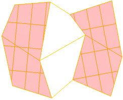
Even subdivision of polygons - Subdivide command :
Current C4D Subdivide command is very limited and rather useless when used
on n-gons.
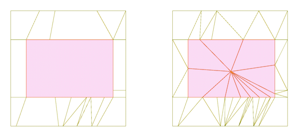
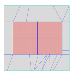
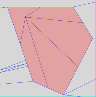
C4D draws new edges from each polygon edge, even if those edges form one straight
line, it also connects newly created points with points outside of the selected
polygon. In most cases such result is useless.
C4D Subdivide command does not provide preview when adjusting its parameters.
Result becomes visible only after Subdivide command is applied.
We need in C4D proper polygons subdivision command similar to one in Softimage
:
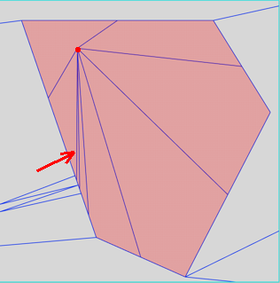
In Softimage subdivided polygon sides made of collinear edges are considered
as one edge, even if made of several edges. As long as those multiple edges
form one straight segment (are colinear), they are considered to be one side
of polygon, and during subdivide operation such side is split in the middle
: Softimage produces what user expects in most situations :
|
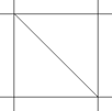
selected n-gon before subdivision
|
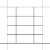
C4D subdivision
|
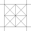
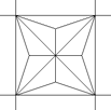
Softimage subdivision (+ type )
|
Softimage offers 4 types of polygon subdivisions: Plus, Diamond, X, Triangles
:
Plus adds edges from the geometric center
of a polygon to the midpoint of each side :

|
1 iteration
|
2 iterations
|
3 iterations
|
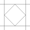
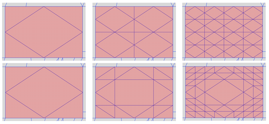
Diamond draws edges connecting the midpoints
of a polygon's sides. It works with tile option (top row)
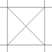
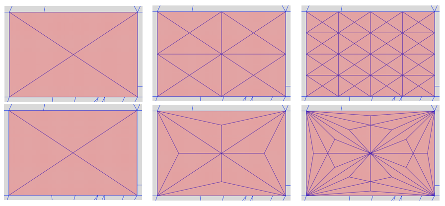
X draws edges from the midpoint of a polygon
to each of its corner vertices. It works with tile option (top row)
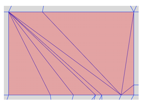
Triangles triangulates all quad and n-gons
:
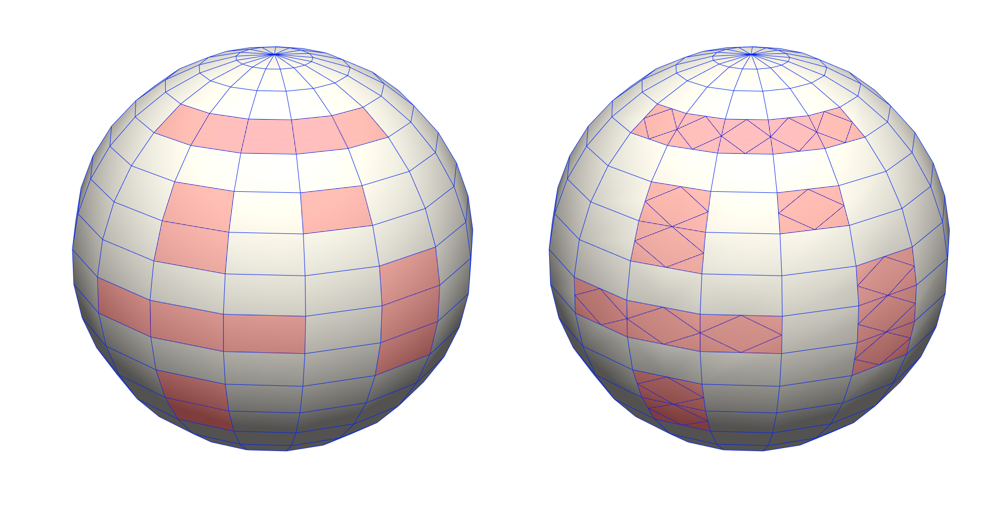
Of course Softimage Subdivide can be applied simultaneously on multiple polygons:
Even Subdivision of Edges :
In C4D edges can be split with: Edge Cut tool, Connect Point/Edges
command and Loop/Path Cut tool (single pair at a time)
Let's compare their usability with Softimage SubdivideEdge in following
example :
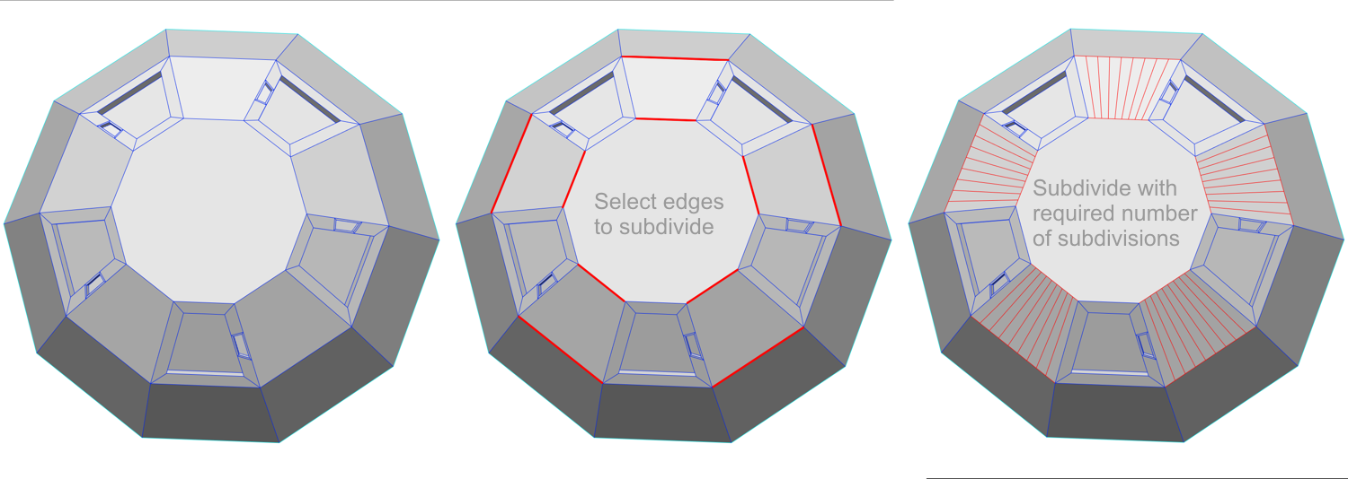
We need to split 9 times, a pairs of edges on 5 n-gons :
In Softimage we just select the edges to subdivide and apply SubdivideEdge
Op with required number of subdivisions :
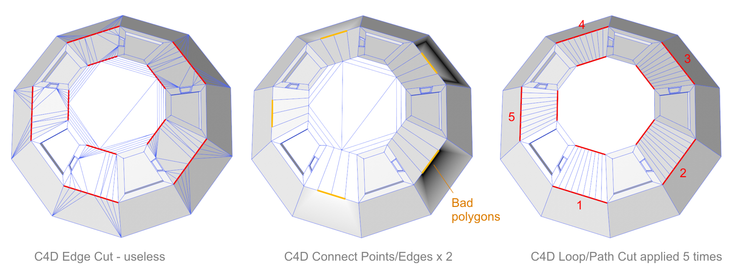
In C4D this is more complicated : C4D Edge cut tool creates rather
useless connections (left image),
|
C4D Connect Points/Edges (center image) applied several times
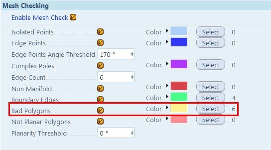
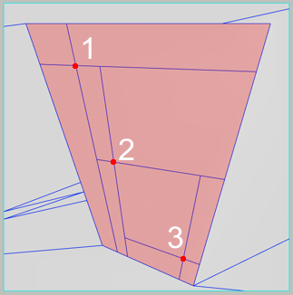
seems to produce more or less what we want, unfortunately it created
bad polygons. Also, when applied in sequence, it can split only to 2,
4, 8, 16 ...
On single pair of edges, C4D Loop/Path Cut can be successfully applied,
but if you have to split many pairs, it becomes annoying, because you
need to split each pair, one, by one. In our case Loop/Path Cut had
to be applied 5 x to produce what Softimage can do basically in one
click.
This is why we badly need a proper subdivision tool for edges in C4D.
It could be achieved by improving C4D Edge Cut and Connect Points/Edges
tools.
|
|
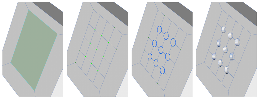
Why proper n-gon subdivision is needed in C4D ?
Eg. to quickly create arrays of holes on a polygon using point bevel :
Splitting of single polygon :
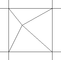
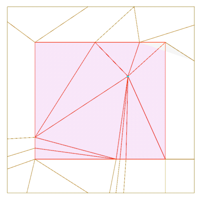
C4D Create Point tool provides just one way of splitting a polygon
when a point is added inside the targeted polygon - new edges are created
from clicked point to some of polygon vertices, the rest is randomly
triangulated. Such result is usually useless :
Effect of C4D Create Point Tool :
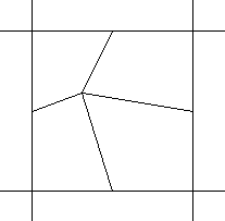
Sofimage Split Polygon Tool offers more clever options
:
|
 |

|
Original n-gon
|
Left click
|
Middle click
|
Right click
|
|
Notice that Split Polygon tool operates on just one polygon at a time
: It splits the polygon currently under the mouse pointer. It ignores
any selections of polygons.
|
When applied on non-quadrilateral n-gon, the Cross-split is similar
to Edges Midpoints split, the difference is that Cross split draw
new edges to n-gon sides (considering colinear edges as one edge),
while Edges Midpoint split draw new edges to all edges :
|
|
|
|
|
| An n-gone split 3 times with 3 consecutive left clicks (Cross
split) : |
Cross split
|
Edges Midpoints split
|
Dicing of multiple polygons :
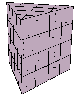
C4D loop cut tool allows dice single polygons, if applied two times, but
C4D lacks a tool to dice at one run multiple selections of polygons.
 |
 |
|
Dicing whole object
|
Dicing selected polygons with defined XZ values 2
and 5 and in Grid mode
|
Please refer to description on the right side of Softimage Dice Polygons
tool for suggestions how such tool could work in C4D.
3 subdivision operators in Softimage :
|
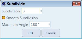
While C4D provides only one tool for polygon subdivision and smoothing,
Softimage offers 3 operators with their distinct parameters:
SubdividePolygons Operator - Subdivides
polygons
SubdivideEdge Operator - Subdivides
edges
Mesh Local Subdivision Op - Subdivide
and smoothens polygons
|
C4D Subdivide tool dialog
|

Description of Softimage Subdivide Poligon/Edges command :
Polygons and edges can be evenly subdivided using the Subdivide Polygons/Edges
command.
Depending on selected components type (polygons or edges) different operators
with different options are used :
For polygons SubdividePolygons operator is used, while for edges SubdivideEdge
operator is used :
SubdividePolygon Op
Divides one or more polygons evenly.
|
 |
To subdivide polygons evenly
1. Select some polygons, polygon clusters, or polygon mesh objects.
2. Choose Modify / Poly. Mesh / Subdivide Polygons/Edges from the Model toolbar
or press Shift+D.
3. In the SubdividePolygon Op property editor, set the options as desired:
Subdivision Type determines the shape
of the new polygons:
Plus adds edges from the geometric center of a polygon to the midpoint of
each edge.
Diamond draws edges connecting the midpoints of a polygon's edges.
X draws edges from the midpoint of a polygon to each of its vertices.
Triangles triangulates all quad and n-sided polygons.
Iterations controls how many times the process is repeated on the polygons
that are created at each step.
A value of 1 subdivides each polygon once; 2 subdivides each polygon and then
subdivides each subdivision; and so on
This option has no effect when Subdivision Type is Triangles.
|
|
|
|
Iterations = 1
|
Iterations = 2
|
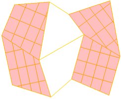
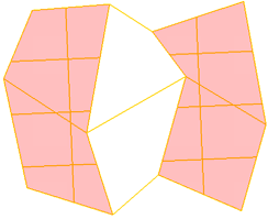
Tile When it is on, all but the last iteration is of the type Plus and the
final subdivision is of the type specified. This gives a tile-like pattern
when working with quadrilateral polygons. When off, all iterations are of
the specified type. Tile has a visible effect only when both Subdivision Type
is Diamond or X and Iterations is > 1.
|
|
|
|
Type X, Tile on
|
Type X, Tile off
|
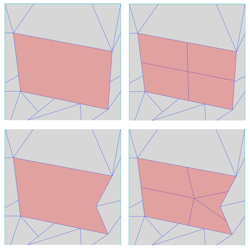
How Softimage subdivision works for non orthogonal n-gons :
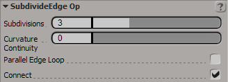
SubdivideEdge Op
Divides one or more edges evenly by adding points, and it optionally
subdivides polygons by connecting the corresponding points on multiple
edges.
|
 |
To subdivide edges evenly
1. Select some edges on a polygon mesh object.
2. Choose Modify Poly. Mesh Subdivide Polygons/Edges from the Model toolbar.
3. In the SubdivideEdge Op property editor, set the options as desired.
Tip: To see the vertices created by the edge subdivision, press T to
switch to Point mode.
Subdivisions The number of edges into
which to divide the selected edges. 1 = no new edges.
Curvature Continuity Modifies the position
of the new point(s) based on the surrounding surface curvature. A value of
0 gives a flat result (no curvature), while 1 gives full curvature continuity.
You can enter smaller and larger values for an exaggerated effect.
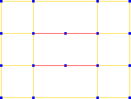
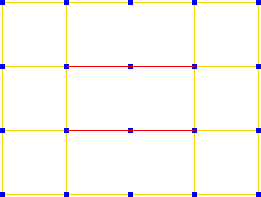
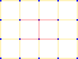
Parallel Edge Loop Adds a new point at
the same position on all parallel edges.
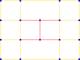
Connect Connects corresponding points
on opposite edges, if multiple edges were selected.
 |
 |
 |
 |
Parallel Edge Loop - OFF
Connect - OFF |
Parallel Edge Loop - OFF
Connect - ON |
Parallel Edge Loop - ON
Connect - OFF |
Parallel Edge Loop - ON
Connect both on - ON |
Two distinct polygon subdivision tools in softimage:
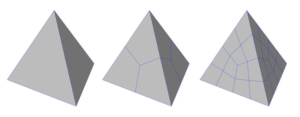
Subdivide Polygon/Edge (described above) adds edges on existing
polygon surfaces without modifying object's shape :
Local Subdivision Refinement smoothens
the geometry with one of two methods :
Catmull-Clark

Doo-Sabin

Description of Softimage Split Polygon tool :
Split Polygon tool interactively subdivide n-sided polygons into n new polygons
:
eg. triangle splits into three new polygons, a quad splits into four new polygons,
and so on.
To split polygons
1. Select a polygon mesh object.
2. Choose Modify / Poly. Mesh / Split Polygon Tool from the Model toolbar.
3. Move the pointer over an existing polygon. The targeted polygon turns red.
4. Do one of the following:
|
|
|
|
|
|
|
|
|
|
|
|
polygon is split using a cross pattern centered on the point
you clicked upon. New edges are created from the point you clicked to
each edge. For quadrilateral polygons, two collinear pairs of edges
are created, resulting in a cross shape.
|
It draws new edges from the point you clicked to each vertex
of the targeted polygon.
|
it draw new edges from the point you clicked to the midpoint
of each edge of the targeted polygon.
|
If desired, you can activate snapping while using this tool.
5. Repeat steps 3 and 4 as necessary.
6. When you have finished splitting polygons, exit the Split Polygon tool
by pressing Esc or choosing another tool.
Notice that SI Split Polygon tool operates similarly to SI Subdivide Poligons
: Polygon collinear edges are considered as one side of polygon, and treated
as if it wasn't divided by multiple points. Only Edges Midpoints split does
not follow this rule, there all edge segments are used - this may be Softimage
bug, as it is inconsistent with other methods.
Description of Softimage Dice Polygons tool
|
Specifying the Cutting Planes
The cutting planes used for dicing are specified by a combination of
the Style, Frame, and Merge parameters in the Dice Polygons Op property
editor.
Style selects the axes to cut along.
The result is a crisscross pattern across the Z = 0 plane (XY), X =
0 plane (YZ), Y = 0 plane (XZ), or all planes (XYZ).
Frame determines which set of axes
to use:
|
|
- Local Component uses the local reference frame of the affected
polygons. The local reference frame can be based on each individual polygon,
each group of adjacent polygons, or all selected polygons, depending the
Merge parameter. Local Component has no effect if whole object is diced
instead of components.
Merge determines how the components are
diced:
- None dices each polygon separately.
- Adjacent Polygons performs one dice operation on each group of
connected polygons.
- All performs a single dice operation on all polygons together,
whether or not they are connected.
|
|
|
|
None : Each polygon is diced individually. In this
example, there are 3 slices in both X and Z, and Frame is set to Local
Component.
|
Adjacent : Connected polygons are diced as one piece
by a 3x3 pattern. Disconnected polygons are diced separately.
|
All : All polygons are diced together as one piece
by a 3x3 pattern. Notice that one of the vertical slices misses the
selected polygons.
|
Number of Slices X Y Z
: Sets the number of slices in each direction using the X, Y, and Z
sliders. The slices are spaced so that they evenly divide the bounding box
with respect to the reference set by the Frame parameter. These sliders are
not available when Grid-like is on.
Grid-like Uses equal spacing between slices
in each direction. The required number of slices is calculated automatically.
Grid Size The distance between slices when
Grid-like is on. Values are in Softimage units.
Point Snap Tolerance : Allows to remove
small edges and polygons created by dicing. Very small edges and polygons
can appear when a slice passes close to an existing vertex. These small components
can be removed using Point Snap Tolerance slider. If a new point created by
the dice operator is closer to an existing point than the tolerance value,
the new point gets snapped to the existing point and welded. As a result,
some of the new edges are no longer exactly parallel to the cutting plane,
but no existing points get moved.
Disconnecting Edges Allows to break the
object apart into separate, disconnected polygons and islands of polygons
along the new edges. It creates pairs of boundary edges instead of simple
edges. The effect is the same as if you selected all new edges created by
the dice operation and then chose Modify Poly. Mesh Disconnect Edges.
Selecting Edge Loops : selects all edges
or boundaries created by the dice operator
