Beveling in Cinema 4D
Main purpose of bevel tool is transformation of sharp edges at corners into
softener, rounded elements, by addition of polygons, but in C4D bevel can
do much more : ex. create round holes by beveling points and extruding, create
complex geometry by defining bevel shape with function graph or even splines.
Bevel can be applied on edges, polygons and points. In each such mode bevel
works differently :
|
Edges
|
Polygons
|
Points
|
Use
It is possible to define bevels interactively in viewport. 3 bevel parameters can be modified with 3 handles, which appear on beveled mesh when using bevel tool : Offset, Depth, Extrusion (Extrusion only for polygons beveling)
Interactive beveling of edges :
Edges are the most often beveled components.
The Bevel tool has a two-level interactivity integrated into it that
works as follows:
• First, click and drag in the Viewport to bevel selected elements
(only Offset will be modified interactively). Release mouse button.
• In the next step, you can now interactively modify the tool’s Offset
and Depth settings by clicking and dragging on the corresponding colored
handles :

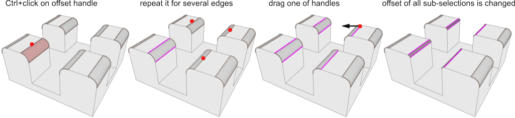
Sub-selection when beveling edges:
You can simultaneously bevel multiple edges, and individually adjust their
offset without having to leave the bevel tool and make another selection.
While using bevel tool on multiple edges, you can change offset for individual
edge, by ctrl+LMB dragging of offset handle.
It is handy if you need to change just a few offsets like this. Buy if you
decide to change let say offset for 10 edges, and need them all to be 3cm,
then it is better to use sub-selection, select all 10 edges, and set their
offset to 3cm :
To define sub-selection Ctrl+click on offset
handle. Sub-selected offset handle changes color.
After you sub-select all edges, you can simultaneously adjust their offset
by dragging one of highlighted handles with mouse, or by directly typing needed
offset value in the Attribute Manager Offset.
To deselect, Ctrl+click on sub-selected (highlighted)
handles.
When sub-selection is active, if you modify offset:
- for sub-selection edges, the current value is applied to all sub selection
edges
- for another edge (not in sub-selection), then all edges change their offset
proportionally.
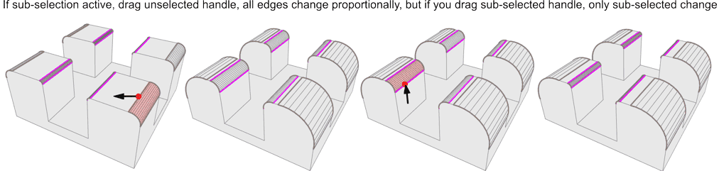
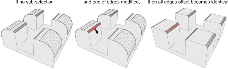
if you turn off all sub-selections, and modify an edge offset, it will be assigned to all edges.
Interactive beveling of polygons :
Two steps beveling :
1st step : grabbing and dragging control
edge with mouse simultaneously modifies:
Extrusion (vertical mouse movement), Offset (horizontal mouse
movement)

Grabbing polygon surface tangles Offset and Extrusion parameters.
Then, when dragged, they are modified proportionally one to another, in order
to produce similar shapes.
2nd step : on newly created rounding edges, depth controls appears (if Subdivisions > 0). Grabbing and dragging them allows to modify depth parameter, which defines bevel "bulging"

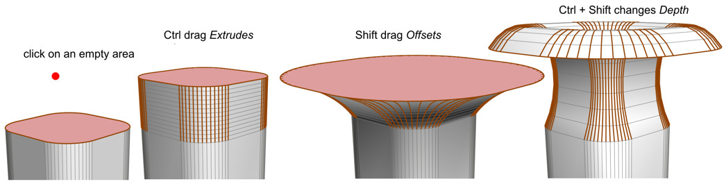
One step beveling:
You can also bevel interactively in "one step", adjusting all 3
parameters (recurrently, if needed). This is how it works : click in an empty
area, hold LMB pressed, and then press following
keys : Ctrl for Extrusion, Shift
for Offset, ctrl+Shift for Depth.
Don't release LMB! If you want to change from
let say Extrusion to Offset, just release Ctrl,
and press Shift, while still holding LMB
pressed. If no Shift or Ctrl
pressed, Offset & Extrusion become tangled. Change selected value
by dragging mouse horizontaly (while still keeping LMB
pressed). Despite this method seems less intuitive at first use, later, when
you get used to it, it gives great way to model things in very fast manner.
Interactive beveling of points :
Basically points beveling works in the same way as edges beveling, except
that in the first step you drag from the selected point, and in the second
step you can only modify Depth parameter by dragging the edge handles
on edges of newly created polygons. (if Subdivisions is >0)
select a point, drag it, when size is OK, release LMB,
click on Depth handle and drag again:
General information about beveling of points:
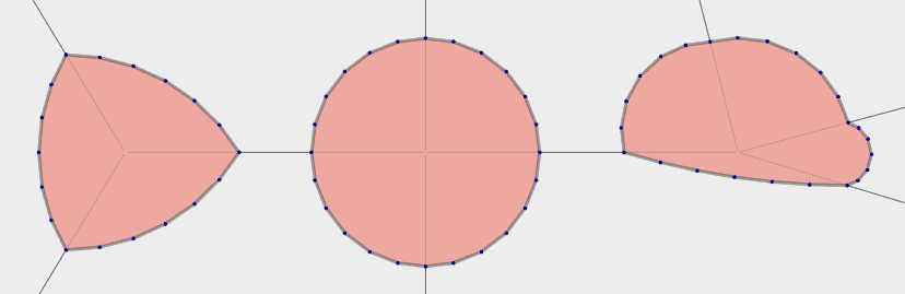
When beveling points, some angle between point edges is necessary to obtain bevel shape. If point lies on a straight line (two collinear edges), bevel just creates points on this line. Bevel shape is "cloned" between two neighboring, non collinear edges. So when 3 edges met in beveled point, the shape will be "cloned" 3 times, if there are 4 edges, there will be 4 "clones" and so on...
Examples of single point bevels depending on number of adjacent edges and their angle:
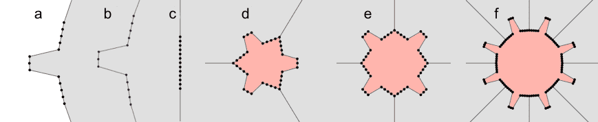
| a. 2 convex border edges,
b. 2 convex internal edges, c. 2 collinear edges - no bevel shape is created, d. 3 edges - shape is repeated 3 times e. 4 edges - shape is repeated 4 times f. 8 edges - shape is repeated 8 times, and so on. |
bevel function defined in User mode |
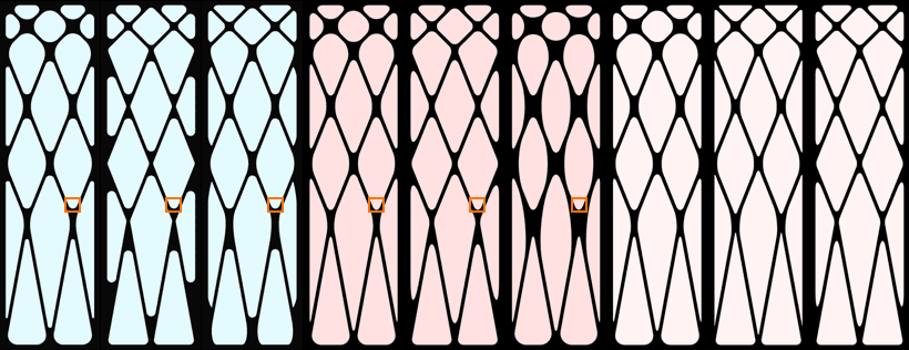
Points beveling can be an interesting method to create holes in mesh. To get regularly shaped N-gons, angles between edges must be equal, otherwise, C4D creates irregular N-gons :
|
Examples of n-gons created by point bevel with following settings: Offset mode - fixed distance Subdivision - 5 Depth -100% Shape - Round Tension 100 Corner N-gons - ON |
 |
Bevel Mode
Edge bevel operates in two modes: Chamfer and Solid
Chamfer - can create simple flat bevels, or rounded ones and
is commonly referred as ,beveling’
Chamfer mode works for all components: edges, polygons and points.
%20in%20C4D.jpg)
|
original
|
chamfer
|
chamfer 1 subdiv.
|
chamfer 4 subdiv.
|
solid
|
Solid - creates parallel edges along the neighboring
polygon. This method is used to accentuate edges on subdivision surface objects
(Solid mode is available only for edges).

Selected edges with Chamfer and Solid modes applied and respective Subdivision Surface object
Chamfer also can be used to accentuate edges, if it is used without any subdivision, the original single edge is replaced by only 2 chamfer edges, while in solid mode you get 3 edges: original edge + solid edge on each side of original edge. In subdivision, more edges means sharper shape, so you can achieve smoother edges in subdivision with simple chamfer edge:
|
Chamfer without subdivisions
|
Solid
|
Collisions Management
Limit option manages collisions between newly created bevel points/edges and other components. Such collisions often happen near sharp corners or with large Offset values. If Limit is switched on, then algorithm merges colliding components to avoid overlapping. However only collisions between some of adjacent components are detected and managed.
|
original mesh
|
limit ON
|
limit OFF
|
If Limit is off, beveled components might move beyond collision limit
and overlap. In such case you can clean the mesh manually. Sometime it can
be useful if you need to ensure that the number of vertices does not change
when the bevel distance is animated.
In most situations Limit option should be enabled, all the time.
|
original mesh
|
limit ON
|
limit OFF
|
Be aware that Limit feature functionality is limited in many situations. It detects and manages just some collisions, so don't expect to get clean bevels in any situation. Sometime a lot of tinkering may be needed on original mesh, before bevel can be successfully applied. Mesh Optimize & edge melt/dissolve tools may be very helpful while cleaning some "dirty" mesh for beveling.
%20in%20C4D.jpg)
| Limits of Limit : above is an example when limit
is set on, but at high Offset values (extreme right) some beveled edges pass through mesh geometry. Sometime mitering mode can affect limit action. on top image Uniform mitering, on right image Default mitering, however limit fails in every case, but in different way : |
%20in%20C4D.jpg) |
Offset
Offset parameter generally defines amount of beveling, but resulting
bevel size may differ upon method used. See below, on Offset Modes
to understand how actual bevel size is defined.
(Offset value can be adjusted interactively using the mouse in the
Viewport)
Offset Modes
C4D offers 3 offset modes modes: Fixed distance, Radial, Proportional.
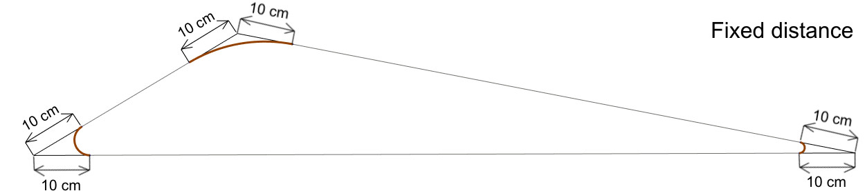
Fixed Distance: the offset setting defines the absolute
value (ex. in centimeters) of the distance between the original, unbeveled
edges and the new edges created by the Bevel tool.
On sharp edges bevel is narrow, on wide angle edges bevel is large.
This mode is similar to Softimage "Along adjacent polygons"
mode.
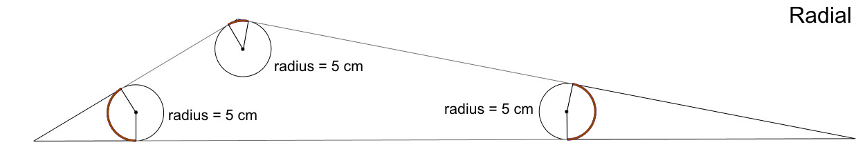 Radial
: attempts to create circular (or spherical) corners of the same curvature,
which the other modes generally do not do. Offset setting defines circle
radius.
Radial
: attempts to create circular (or spherical) corners of the same curvature,
which the other modes generally do not do. Offset setting defines circle
radius.
On sharp edges bevel is large, on wide angle edges, bevel is small.
Such "real" corners are often used in NURBS CAD programs.
Radial mode works only at locations at which 3 edges conjoin at a single point.
(in other cases the Fixed Distance algorithm will be used).
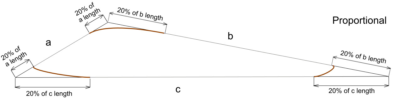
Proportional mode may produce lopsided bevels if neighboring polygons
differ in length, because the % defined by Offset setting is the ratio
between the distance from unbeveled edge to new edge and original edge length.
A value of 50% will make bevels congruent (touching each other - but will
not merge them).
- on wide angle corners fewer subdivisions are needed to get smooth bevel than on sharp ones.
- you can adjust individually all bevels sizes, so they look consistent on whole object.
In Softimage there are 3 offset modes : Bevel width, Along bisectors, Along
adjacent polygons
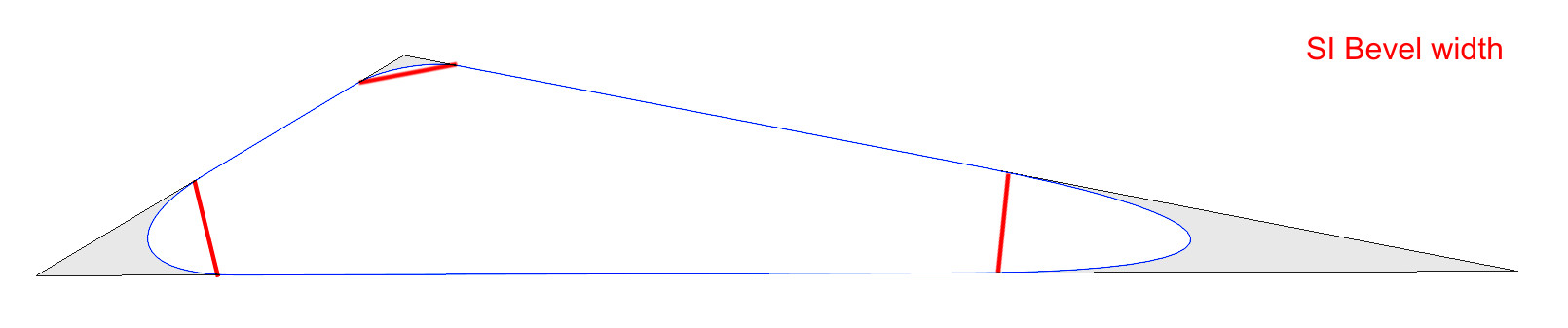


Softimage Along adjacent polygons mode is similar to C4D fixed
distance mode.
When beveling a single edge, mode isn't very important (except C4D proportional
mode, producing lopsided bevels), but when simultaneously beveling multiple
edges on polygons of various sizes and shape the result my be significantly
different upon mode used. Below is an example of beveled wireframe, on which
all corner edges have been selected and beveled in one step :
|
C4D modes :
Fixed Distance, Radial, Proportional with offset values adjusted so the size of bevel in orange frame remains identical. |
Softimage modes :
AAP, Bewel width, Along Bisectors with offset values adjusted so the size of bevel in orange frame remains identical. |
Softimage modes :
AAP, Bewel width, Along Bisectors with offset values adjusted so the average size of "grid weldings" remains similar for all 3 modes. |
Radial offset mode is quite cranky - it works only for edges which are connected
to exactly 2 other edges, and those can't be boundary edges : 
Subdivisions
Subdivision parameter is used to round corners created by the Bevel tool. If set to 0, corners will not be rounded and hard chamfers and edges will be created. Higher values should be used in particular in conjunction with the Shape value described below to create rounded (’soft’) edges.
Depth
|
Depth parameter "blows" rounding effect in or out.
The Depth value can be adjusted interactively with mouse in
Viewport 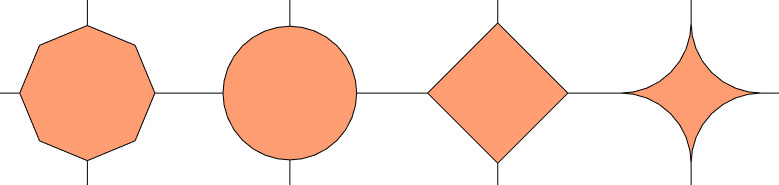
|
|

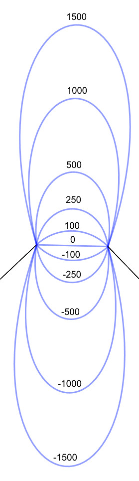

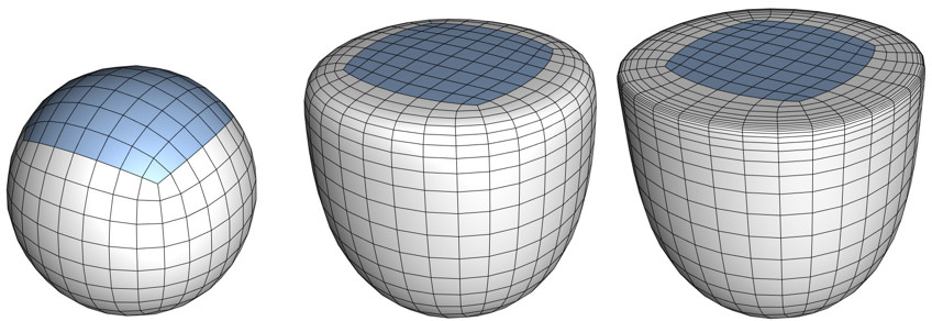
Below is an example of Depth & Subdivisions parameters action on cylinder's beveled edge:

|
D=-500, S=2
|
D=-240, S=1
|
D=+500, S=20
|
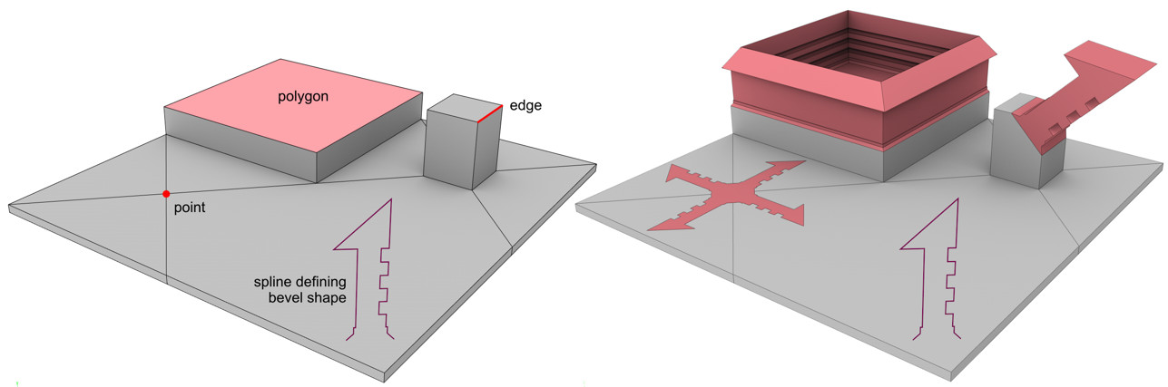
Shape
When applying bevel to components (points, edges, polygons), edges and points
get dissolved, and a new geometry is created. This new geometry can be given
any new shape :
There are 3 ways of defining the shape of this new geometry: Round, User
(graph), Profile (spline)
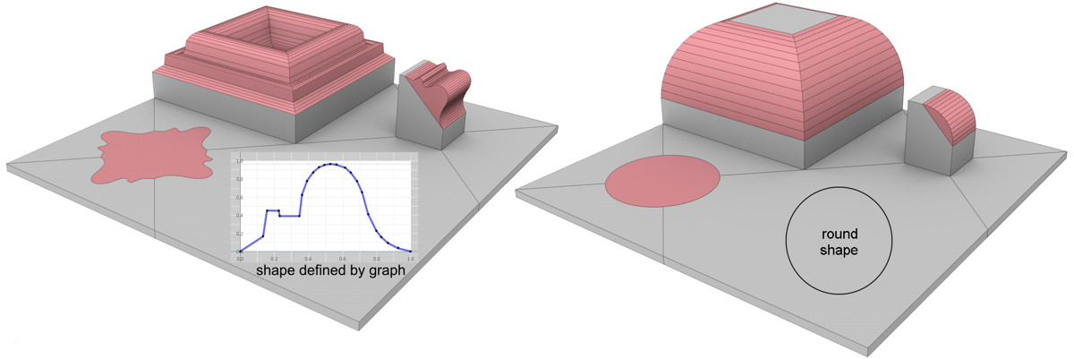
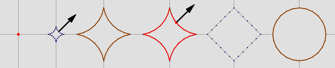
Round Shape mode
|
Tension defines subdivided edge bulging. (Subdivisions must be >0) >100 - sharpen, hyperbolic shape100 - circular 0-100 - flatten 0 - flat (as without subdivision) < 0 - bulged, elliptic shape Direction of bevel depends upon original edge shape: |
 |

Shape defined by function graph
In User mode, a function graph is used to shape the original edge. If Symmetry is disabled, the function graph’s shape can be imagined directly between both diverging edges (the Depth setting defines the direction and scale of the curve’s modification). Set Subdivisions to a value that will reproduce the curve as accurately as possible.
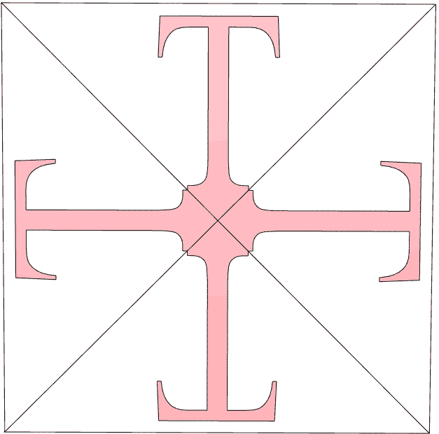
Tip : Use graph curve to shape simple curves (pict.1), more complex shapes won't be precise enough with few subdivisions (pict.2), more subdivisions may be applied, but then you get a heavy mesh (pict.3). If more complex and well optimized bevel shape is needed, it is better to use spline based profile (pict.4). Spline profile even allows to create "overhangs" like T letter, which is impossible with function graph in User mode.
Symmetry : Mirrors function graph
Constant Cross Section Depending on the edge to be beveled,
a tubular effect (with regard to the rounding volume) can result if the User
or Profile modes are used. If Constant Cross Section is enabled,
this effect will remain more-or-less constant (especially at corners).
|
Constant Cross Section OFF
|
Constant Cross Section ON
|
Shape defined by spline
Profile Spline When in this mode you can freely define the shape
of a beveled edge. A spline can be used to define the shape of the edge to
be dissolved. The subdivision will be defined by the spline (the Bevel
tool’s Subdivision setting will have no effect).

Spline pre-requisites:
• Open spline
• Profile Plane should reflect plane on which spline was created.
For example, if you create the spline in the Front view, XY
plane should be defined.
• Axis must be correctly defined:
ex. if spline on XY plane, spline start and end points should be positioned
on spline X axis. 
Assuming the Profile Plane is set to XY, the bevel will take
place along the object’s X axis and will include a variance in the Y direction
in order to create the bevel edge shape. In the image above, you can clearly
see why the axis orientation at the left, which is created more-or-less automatically
when the spline is modeled, fails. The best method is to set the object axis
to the spline’s starting point and rotate it so the spline end point lies
on the X axis. This produces decent results because the spline is positioned
as an edge between the edges diverged by the Offset setting. The Depth
setting must be used to adjust the size of the concave or convex bevel!
Note that problems can occur when beveling 2 or more edges that meet at a
given point.
Profile Plane defines the plane (object coordinate system!)
in which the profile spline lies. This is important for the orientation of
the object axis, as described above.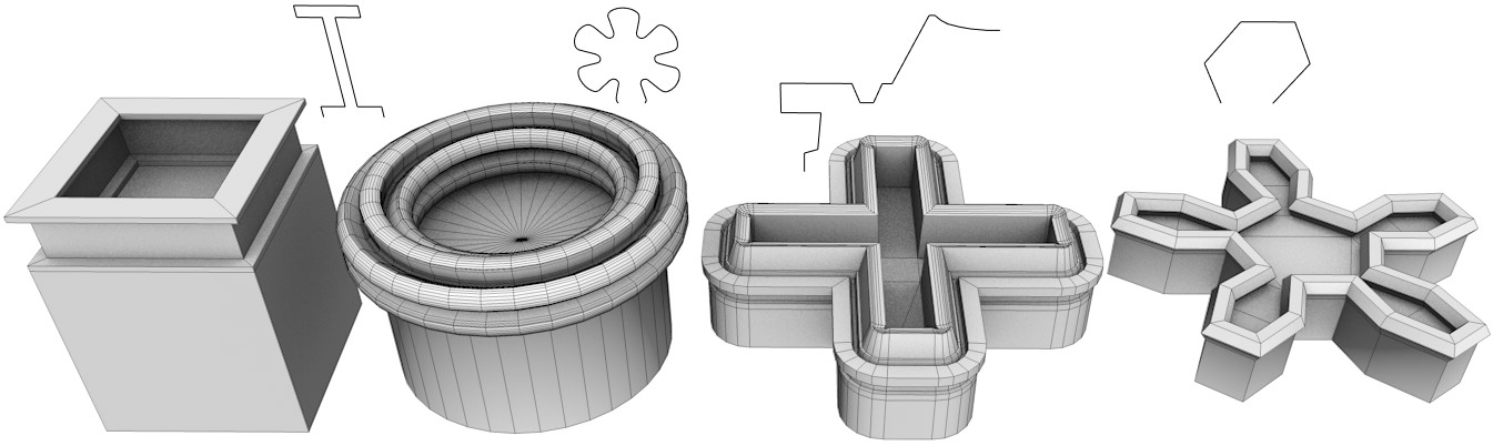
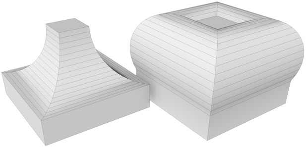
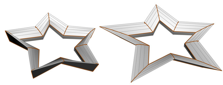
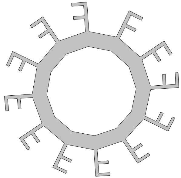
Polygons bevel with spline profiles
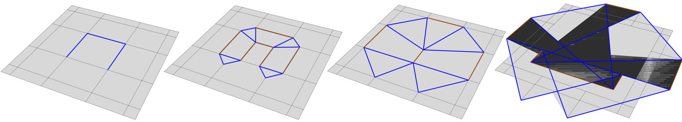
Points profile bevel let quickly create very complex, flat shapes :
|
To get effects as on picture above, ensure that beveled points are
connected to just two edges and are on an N-gon outer edge.
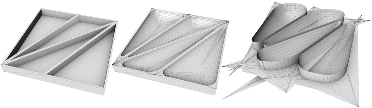
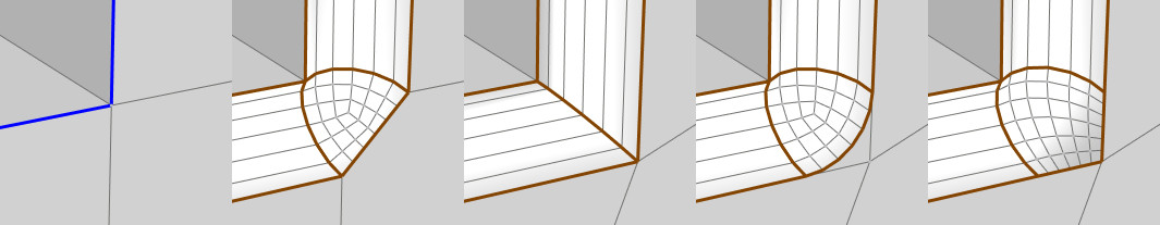
C4D spline bevel sometime reverses (mirrors) beveled profiles : |
|
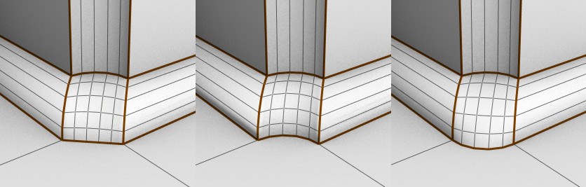
Mitering
Special bevels require special settings. This also applies to Mitering. Mitering
points are one of the most difficult aspects for beveling. These settings
are designed to help solve these problems. What is mitering in C4D? If you
select a continuous edge that runs along multiple polygons, a mitering is
a common point of two selected edges where more than 3 polygons meet.
If such an edge is beveled, this method can be used to dissolve a corner point.
When a continuous edge passes by a point where > 4 polygons met, various
mitering strategies can be applied. If just 4 polygons met, then each method
produces same result as uniform.
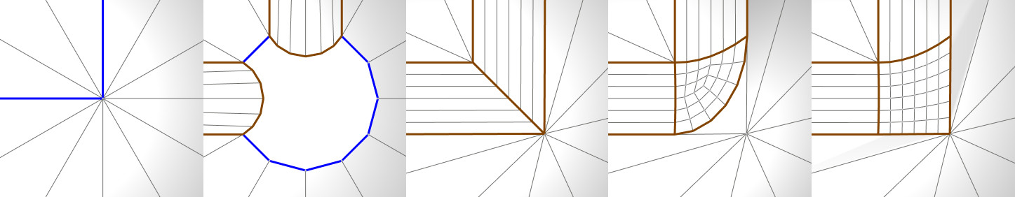
|
Default
|
Uniform
|
Radial
|
Patch
|

If angles are uneven, only Uniform mode provides good results. If
you have multiple coplanar polygons, consider to melt them into one n-gon,
then each method will work nicely : 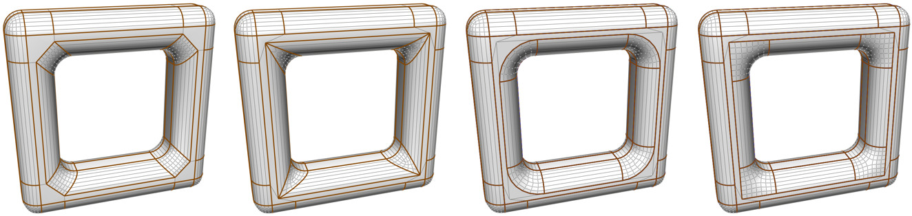
|
Default
|
Uniform
|
Radial
|
Patch
|
Uniform mode is the only mode that does not create N-gons on surrounding
polygons, but it moves the geometry.
Uniform miter option controls the tesselation at junctions between two beveled
edges:
In default mode 2-edge junctions with >2 polygons on the same side are
tesselated by polygons in order to preserve the surrounding geometry.
In uniform mode, all 2-edge junctions are single edges. This may result in
cleaner geometry in the beveled region but may also change the shape somewhat
in the surrounding areas.
|
Default
|
Uniform
|
Radial
|
Patch
|
|
Default
|
Uniform
|
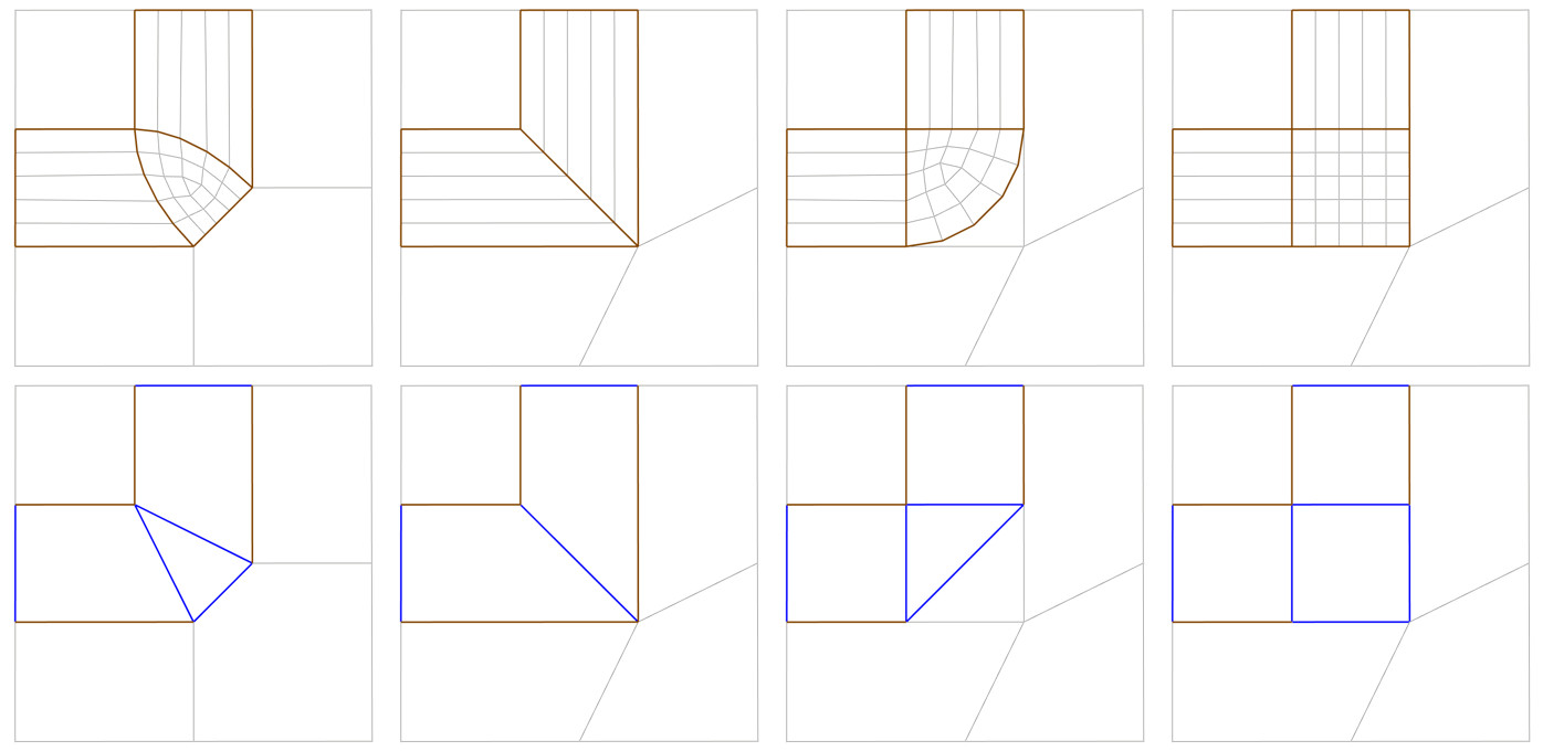
Partial Rounding
Partial Rounding option might be useful only in special circumstance
when beveling 3 selected edges (and 2 unselected) and neighboring edges that
meet at a point. Like building corner.
It works only with Topology / Mitering / Default mode and Subdivision
> 0
The edge that lies at the ,tip’ will be affected as follows:
|
None
|
Full
|
Convex
|
• None : tip edge is linear
• Full : tip edge is rounded taking the Depth setting
into account
• Convex : A difference between Full and Convex
can only be seen if Depth is set to a negative value. Convex
will then let the ,tip’ and its opposite (yellow) edge assume convex (=outward)
shapes, which is the only way the ,tip’s’ mesh can face outwards
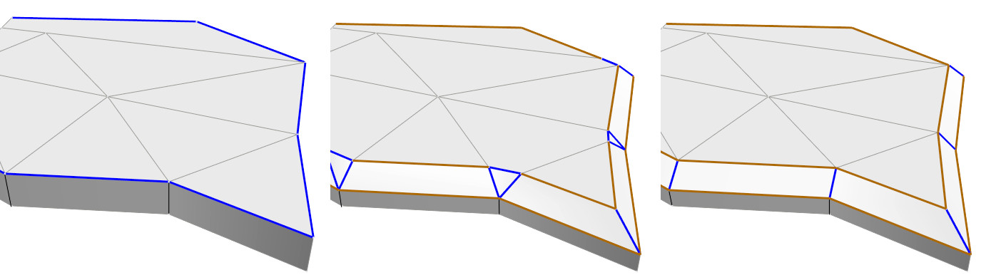
Ending
Ending : defines how the transition from rounded to non-rounded edges should take place, when edge to be beveled meets an edge that should not be beveled
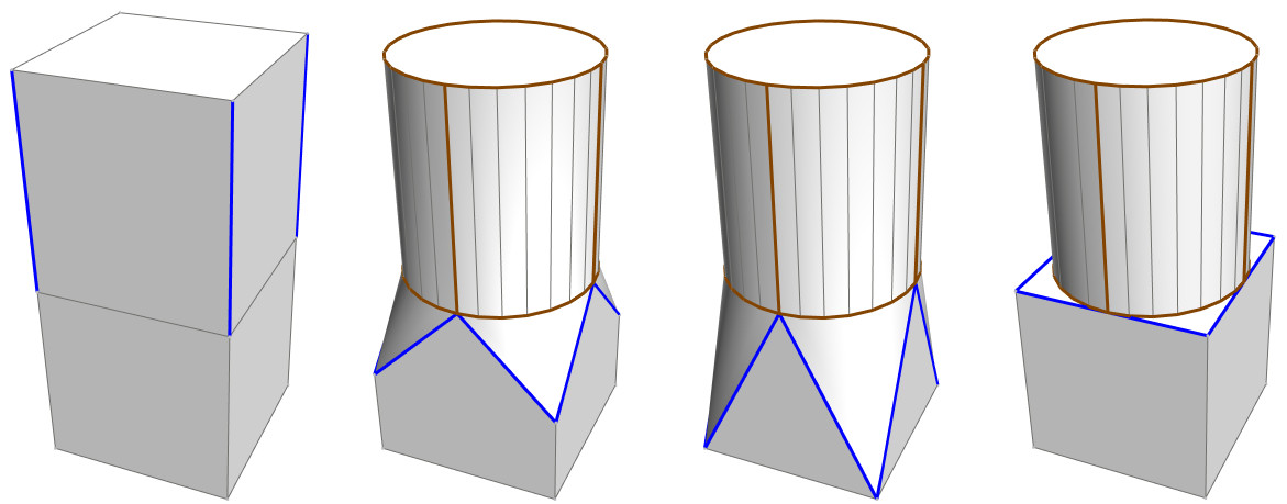
|
Initial state
|
Default
|
Extend
|
Inset
|
 Initial state |
 Default |
 Extend |
 Inset |
Default : As was the case with bevel tool prior to C4D R15,
the transition occurs along the unbeveled edge(s) (independent of the Offset
setting).
Extend : transition takes place along entire length of non-rounded
edge(s).
Inset : an abrupt transition is created, with a hard edge. Non-beveled
edges remain unchanged.
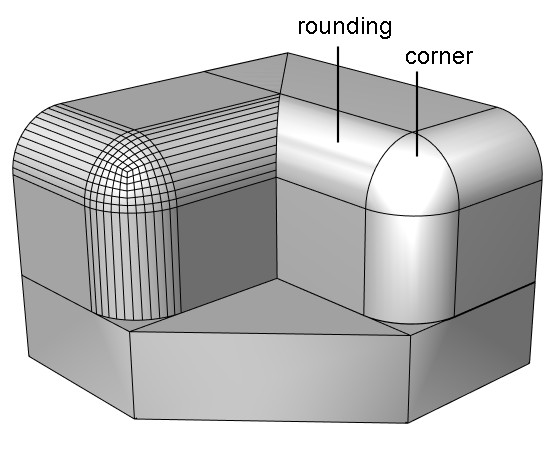
Corner/ Rounding N-gonsoptions define what kind o polygon should be created on roundings and
corners. Left: Corner N-gons and Rounding N-gons enabled; these options disabled at right. |
 |
Phong Break Rounding / Miters
options allow to break phong shading along newly created outer edges (Phong Break Rounding) or at the Miter points (Phong Break Miters)

|
All OFF
|
All ON
|
Rounding ON
|
Miters ON
|
|
For soft bevels with numerous subdivisions, no breaking make sense,
while if you need just simple chamfer (no subdivisions), in such case
phong break on rounding and miters make sense. |
 |